Breaker Coordination Considerations For Switching Mechanical Load In Data Centers
Breaker coordination is a fundamental consideration in any electrical design. You hear stories, in poorly coordinated facilities, of a light going out in a parking lot and taking out the entire building. These types of failure mystify many, but the reality is there is usually a good explanation.
DX Cooling In The Data Center
Distributed redundancy in data centers offers many opportunities to reduce equipment overhead. Take, for example, a 4N/3 infrastructure. This type of design would dictate that with 15 HVAC units, you would require 20 distributed equally across the four feeds to account for a worst-case failure on the single feed.
The design mentioned above also does not consider simple operational considerations such as “down for maintenance” scenarios that are persistent in a large population of CRAC units. Add an extra 1 to each of the feeds, and you quickly arrive at 24 HVAC units needed to satisfy the requirement and concept of operations for the design of your facility. The proper design represents a 60% equipment overhead – far greater than the 1.33x overhead that a distributed redundancy architecture yields.
Each additional unit adds an extra unit, as well as the associated installation.
It’s no wonder that chillers represent the predominant design methodology for many data centers, large and small. The common piping allows you not to suffer from the challenge of modularity, thereby reducing the design cost. The CRAH floor units, which would carry the same consideration as the CRAC units mentioned above, cost as a function of overall cooling pale compared to bringing the full burden of a packaged DX system.
In conclusion – Traditional chiller design yields a cheaper $/kW, which is why people choose it.
Fault Tolerance: Things to Consider
Unfortunately, it is challenging to achieve fault tolerance with chillers. There are many examples of poorly executed chiller designs in the industry, and not even experienced operators are immune to the issues associated. Compound this with the fact that DX units require careful Coordination with the building’s physical architecture versus a “send it anywhere approach” with water. Most data centers “settle” for Concurrent Maintainability with chiller design, which means that a single fault could take the entire facility down.
The above example discusses a 60% overhead with a distributed redundancy design, now consider a small data center that does not have the scale capable of distributed redundancy and utilizes a traditional 2N infrastructure. At its most basic level to meet 2N, you would require two AC units, one on each feed, which is a 2x overhead.
The operational consideration of fault tolerance during a single planned maintenance is often desired, which quickly jumps you to four units, which would be a 4x overhead. Things rapidly get unreasonable.
We can move that number by increasing the data center’s modularity where the base requirement is three units, for example. We would then require a total of 8x units, four from each feed, an overhead of 2.667. We are still well more than 2x.
What Would We Recommend?
DX design in a properly fault tolerant data center has more problems than just paying for a lot of equipment to sit around. Lightly loaded units, even with tandem compressors, are susceptible to short cycling, which can compound humidity and shorten the lifetime and performance of the equipment. In practice and in conversation with reps from Liebert, the units “prefer” to consistently loaded to a minimum of 25%, and 35%+ is even better. On a cold day, under actual loading conditions, or during states of change, this can be difficult to achieve since typical design conditions target 80% loading at peak under a failure condition.
Furthermore, the system is not defensible to shrinkage, where the total heat load of the room decreases as the IT load displaces to colocation facilities or the cloud, or as equipment fundamentally increases in efficiency. Chillers also suffer from this problem.
With dual power fed units, the circumstance changes considerably. Consider a 2N infrastructure with two switched CRAC units. One is down for maintenance, and a utility feed was to fail. The remaining CRAC unit would then switch to the redundant feed. This essential redundancy worked with two units or a 2x overhead.
Switching in a fault-tolerant introduces a large number of essential considerations that must occur to maintain fault tolerance. With proper coordination and settings, even theoretical fault situations that reside outside of the scope of “Selective Coordination,” Rulesets can be solved. The Uptime Institute’s guidance to switching in a data center environment is that switched load shall have ground fault protection between the switch and the load to prevent the transfer of a fault. Beyond that, they investigate these topics of Coordination to achieve fault tolerance.
With proper design, switched DX can yield a fault-tolerant infrastructure that will serve you for many years. However, if you are not comfortable with switching, un-switched DX can still be extremely economical in a distributed redundant environment. We think that this design provides a great path forward for achieving real fault tolerance at the edge and smaller to mid-size corporate facilities. If you find that you are not comfortable with meeting these needs or designing to these very specialized conditions, it may be best to go into a colocation environment like our Houston Datacenter.
Our Breaker Coordination Insights
1. Don’t take the package deal
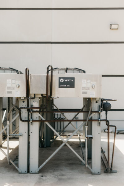
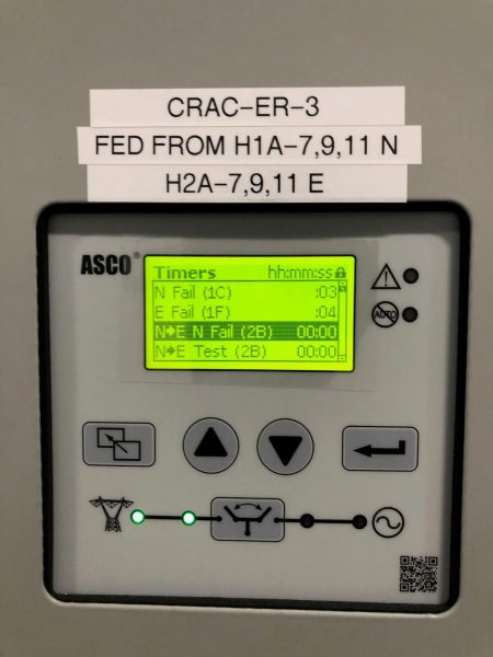
Some HVAC manufacturers like Vertiv/Liebert offers switched functions as part of their HVAC package. Do not assume that the default functionality provided has the appropriate protection after the switch and that it will coordinate with your distribution up-stream for fault tolerance. We recommend forgoing the packaged switched functions and utilizing a custom switch such as the ASCO 300 Series. These units offer greater separation between the incoming feeds that provide some degree of fault protection and programmable settings such as transfer delay, which we will discuss below. Around that, additional breakers should be added that coordinate properly to the need.
When we were recently doing a design, we wanted to see if the default fuses would selectively coordinate with upstream breakers without placing a ground fault rated breaker. The theory is that the breaker would be small enough not to trip upstream breakers regardless of the type of fault or incident energy. We found that the fuses did NOT selectively coordinate under all circumstances, which necessitates a custom design beyond the package deal they provide. These results vary by the type of distribution you have upstream, but as a general rule, almost all distribution will not coordinate comprehensively.
We would recommend placing ground fault rated feeder breakers on each side of the switch (they may be in the panel) to prevent the propagation of failure for the several feet of wire between the switch and the ground fault rated breaker down-stream.
2. Size matters – Modularity counts for Coordination
The units’ size relative to the distribution they are coming from is relevant for the Coordination under various worst-case scenarios. With proper Coordination, we meet selective coordination loads for most types of faults and overloads with a simple feeder breaker.
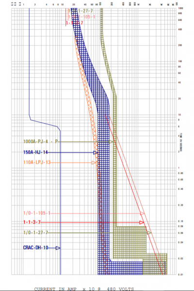
The maximum incident energy possible at the switchgear was determined to be around 20 kAIC. We see a slight overlap on the above log-log breaker coordination curve on an extremely HIGH instantaneous fault current in the 15k-20k range. This scenario is almost theoretical because it would generally be an extremely hard fault that starts with that level of transmission. Most faults related to insulation or motor failure just don’t follow that type of phase to phase fault. >90% of faults start as a ground fault, which we will discuss in a minute. Two scenarios here would be if a technician, while installing and commissioning the unit, bolted two phases together or left a tool sitting between the two phases of the lug, which provides that instantaneous, massive fault current. Outside of that theoretical situation we do not see any issues. Selective coordination rules accept this curve.
Not pictured here is the primary distribution breaker above that, which is 2000 amps. We found that under no circumstance do they cross; the 150A feeder just does not create enough energy ever to trip it for phase-phase type faults. This conclusion makes us very comfortable that we could not trip the main even with a hard fault.
The conclusion from the study is that the size of each portion of the motor load should be considered with respect to the size of the feeder servicing it up-stream. Too large of a single, centralized load (like chillers or too-large CRAC units), can propagate faults upstream and compound issues. With modularity, and proper placement of ground fault rated breakers, we solve for all selective coordination and fault tolerance situations, even resolving theoretical faults that reside outside of the rules of selective Coordination.
3. Faults in and around the switch
If a technician did place a tool across the lugs, which is unlikely, the system COULD trip up the 1000 Amp breaker. In this circumstance, we would lose our mechanical distribution panel for this feed. We accept this per the design, but what we wouldn’t want to have happened is that the transfer switch then transfers that fault over to the redundant feed. That is why we change the ASCO unit’s default settings to have an initial transfer time delay of some time greater than zero. The amount of acceptable time is dependent on the thermodynamics of your room under transient failure scenarios needed to meet continuous cooling requirements. A fault would only expose a maximum three units for us, so we chose 10 minutes because we don’t need those units immediately or at all, but we would prefer to have them before too much time has elapsed. In general, we recommend some time greater than a cold-start time for a generator so that you are not spuriously switching. Some slow time reaction allows for the source of the fault to clear, such as the tool getting pushed away from the lugs after the breaker trips. We would also recommend staggering retransfer time delay on your feed so that you are not introducing unnecessary transients into your system, recovering from an unlikely total single feed failure.
Transfer time delay is also extremely important for practical purposes: you do not want to “hit” mechanical load with line voltage (especially if not synchronized with the original load) too quickly.
Ground faults are the most crucial piece of Coordination that needs to occur, having addressed the less frequent types of faults with the inherent design of the regular breakers themselves. Compressors while operating into a failure state, typically ground. Insulation failures usually ground.
Ground fault protection is generally in the instantaneous range will trip up to your next available level of ground fault protection. The ground fault will defeat the entire regular curve shown above and may hit the instantaneous of breakers further upstream.
Most facilities utilize a minimum of two layers of ground fault protection, which would be the first mechanical panel for our feeds. To be clear, with a switch in your environment, this is not enough. At a minimum, an additional breaker must be added between the switch and the load in the distribution point to prevent the transfer of fault to the top level of two redundant systems.
Fortunately, with our distributed redundant design for our datacenter, we anticipate that an uncoordinated ground fault would take down five units maximum with two full panel failures with NO ground fault breaker at the switch. Interestingly, our design yields an acceptable cooling level due to the overhead of capacity that we employ as compared to typical facility loads. (80% of 2250, with 3000kW of HVAC load distributed across 20 units at planned capacity, 60-75% of that at “typical” seen capacity.
However, many smaller facilities don’t benefit from cooling capacity fault tolerance that our distributed redundant yields – take a 2N line-up, for example.
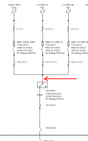
Here, we would want to provide the ground fault rated breaker south of the ATS, which will take the load out and prevent the transfer of a fault. We utilize this design as well as a matter of good hygiene. Another line of defense for a traditional 2N system would be two create two mechanical panels – one that feeds “primary source” and the other as a dedicated “secondary source” panel. Separate panels would allow for the ground fault if it did bypass the first line of defense of the ground fault rated breaker on the load side of the switch to trip the upstream breaker only servicing the redundant feed on the HVAC units, thereby not disrupting the operation. This would increase the typical single feed panel count from two to three, yielding a total of four, including the main distribution for that particular feeder.
4. Nuisance tripping
With any type of breaker or ground fault protection on mechanical loads, nuisance tripping is a significant risk. Careful Coordination and analysis of the load should exist to ensure that tripping does not occur. The most typical form of nuisance tripping is asymmetrical inrush current on startup on compressors and units. This asymmetrical current is caused due to imperfect resistances in the compressors’ windings, and can, for a brief period trip, delta configured ground fault breakers into thinking a fault has occurred.
The frequency of nuisance trips can be tested by introducing a single breaker into the population and name-plate analysis.
Considerations for continuous cooling
The entire purpose of switching with HVAC is to provide an economical and reliable way to provide cooling for the facility. Steady-state cooling capacity under various failure states must also function as well as transient changes while in a state of recovery.
————–—
Tying it all together
The Uptime Institute makes excellent recommendations for providing ground fault protection after the switch. We highly recommend that anyone performing any type of switching, even if the manual, consider this edict. We chose a three-pole 150-Ampere Square D Powerpact HG circuit breaker with a Micrologic 6.2A trip unit (LSIG) for this purpose. The types of breakers here are expensive but provide the proper protection required to safely utilize any kind of switching in a data center environment. The use of any switch should be carefully considered before implementing, but can be done safely if done correctly.